
First solder your ESP to a Prototype-board, because the Solder-Points of the ESP only have a distance of 2 millimeter. So if you like to work with prototype-boards with the distance of 2.45 mm between the holes you should do that. Therefor use a prototype-board which has dimensions of 10x12 usable holes.
Then Connect the ESP
which is soldered on the board on a breadboard. You can do this with
long wires or you can use two Breadboards and plug the ESP on top of
the „Supply-Channels“.
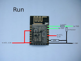
To Run the
ESP-Module, like run AT-Commands Connect the Module like this. TX and
RX go to a USB to TTL Converter which is plugged into your computer.
GND and 3.3V go to an external power-supply. Now you can check with the AT-Commands which you can send with the Serial Monitor of the Arduino IDE or with Putty to the ESP if all works correctly.

